After a great deal of deliberation, it has been decided that this engine was rebuilt using an original 150cc, Innocenti Cylinder, Head and Piston (uprated from it's factory 125cc top end), but maintaining the 12 volt conversion. The main reasons for this is that the old points system was prone to be unreliable and likely to create unstable performance for the owner. A brand new 12 volt system gives improved reliability as well as uprated performance for lighting and starting etc. It was also felt that the option to fit the Mugello conversion may have priced this scooter out of the reach of the normal rider. However, the Mugello can still be fitted if required as an option for whoever is eventually lucky enough to own this machine. Armandos will talk this through with the new owner.
As previously stated on this blog, engine building is quite different to scooter building, and this has never been my area of expertise. Maybe next time we study the rebuild of another model, the strip and rebuild of the engine will be included. But on this one, the engine was built at Armandos, whos 30 odd years at least building these things, I can never compete with.
For those of you who wish to undertake this part, here again is the link for a complete engine rebuild that I have put on the LCGB web site.
http://www.ilambretta.com/engine.html
Here is our engine now. Complete and totally rebuild by Guido Pastorelli at Armandos. It has brand new internals that includes oil seals, bearings and so on. The 'top end' is standard 150cc.
First I will attach the cylinder head cowling seen below. There is a bit of a knack to this, which if you follow, will also help you remove it shoud you need to for running repairs.
First, take out the spark plug.
What you see here, is the inlet port on the cylinder head where the carb will go. The carb is attached by two studs. Here you can see one has been left in place as a guide for the gasket to go on next. First, use a thin film of grease, on to which you place the gasket.
Now place the gasket over the stud. Make sure your gasket is oriented correctly. Some of them will only fit the right way round. Check yours by looking down the opening to make sure the gasket is not covering any part of the inlet hole.
Again, apply a thin film of grease to the top of the gasket.
Now slot the carb manifold over the stud that was left in place and adjust the position until you can see down the apperture that the second stud can be inserted.
The two nuts can now be tightened down on to the studs to secure the manifold. Do not overtighten. You do not want to strip the threads in the cylinder head. Get them tight and then a small nudge to finish. The compression on the gasket to seal it will do the job. You should be able to 'feel' when to stop.
Push some old rag on to the manifold opening to prevent anything dropping in to the manifold and down in to the barrel.
Flip over the engine and on the underside, you will see the inlet port for the exhaust. Follow the procedure as above with grease etc.
The gasket for the exhaust downpipe on this model is copper. This is used once as it is crushed when tightened. If you have to remove your exhaust downpipe at any point, buy another gasket.
Now place the exhaust downpipe on to the exhaust port, using the two studs and 13mm nuts, each with a flat washer but DO NOT TIGHTEN. Just put the nuts on the end of the studs for now. We need to be able to move the downpipe around for a little while in order to get the head cowling on.
This shot shows which way around the brass exhaust nuts should go.
Now, by lifting the downpipe out of the way, you can slip over the cylinder head cowling. I do it this way around because although it is entirely possible to put the head cowling on first and THEN put on the carb manifold and exhaust downpipe, it is much harder to tighten up the nuts because of access being made almost impossible by the cowling itself.
You can now tighten up the exhaust downpipe. Again, do not overtighten.
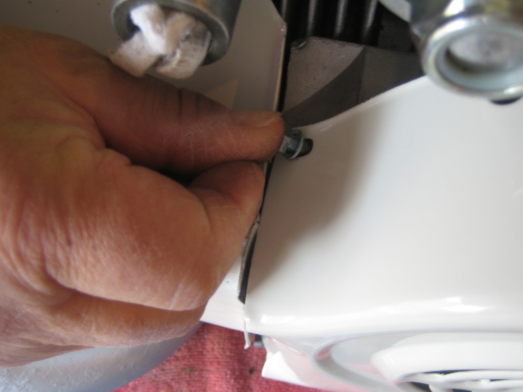
With the engine still upside down, fit the two bolts along the lip of the cowling. These as M5 8mm headed bolts. Use a flat washer with each. Do not tighten them up just yet. Leave them loose to allow the cowling to move until the head bolt is in place.
This is the larger bolt that goes in to the hole at the front of the head cowling. It is screwed in to the large nut that is threaded right through and attached to the relevant cylinder head studs. This dual function nut allows you to use it to both tighten the cylinder head and secure the cowling with the nut show below. This is a specific bolt with a 14mm head, using a flat washer. With this in place, you can now tighten up the nuts on the cylinder head cowling.
Now put in a spark plug. This again, will prevent anything dropping in to the barrel while you work.
Now we will attach the flywheel cowling.
Simply slip the cowling over the flywheel mag housing, making sure that the 'curved in' tab goes INSIDE the cylinder head cowling. Other than that, it is a simple fit.
Go around the outer lip, inserting M5, 8mm headed bolts with flat washers. There are 5 in total. Leave the very upper one until last and do not tighten any of them until all of them are in place. This will allow you to move the cowling slightly to line up holes on the cowling with those on the mag housing.
Before you tighten ANY of the flywheel cowling bolts, make sure the holes at the top line up. Now you can tighten them.
Finally, insert the last bolt in the uppermost hole but do not tighten. You can leave this for now as it will need to come off again later.
Engine cowlings are finished.
Eagle eyes spotters may have noticed two things.
1. I forgot to put the dust cover on the flywheel before attaching the cowling. We took it off and corrected that.
2. We have not used the rubber damper washers that are usually inserted in to the extra holes you will find around the edge of the flywheel cowling. The main reason being that they offer very little in the way of benefit from an anti vibration point of view and do make attaching the cowling considerably more difficult.